What is the biggest integration risk?
The handover between feeder chute and capper is often the biggest risk if it is not planned early.
Guide
Use this checklist before adding a cap feeder to a new or existing capping machine.
Specification focus
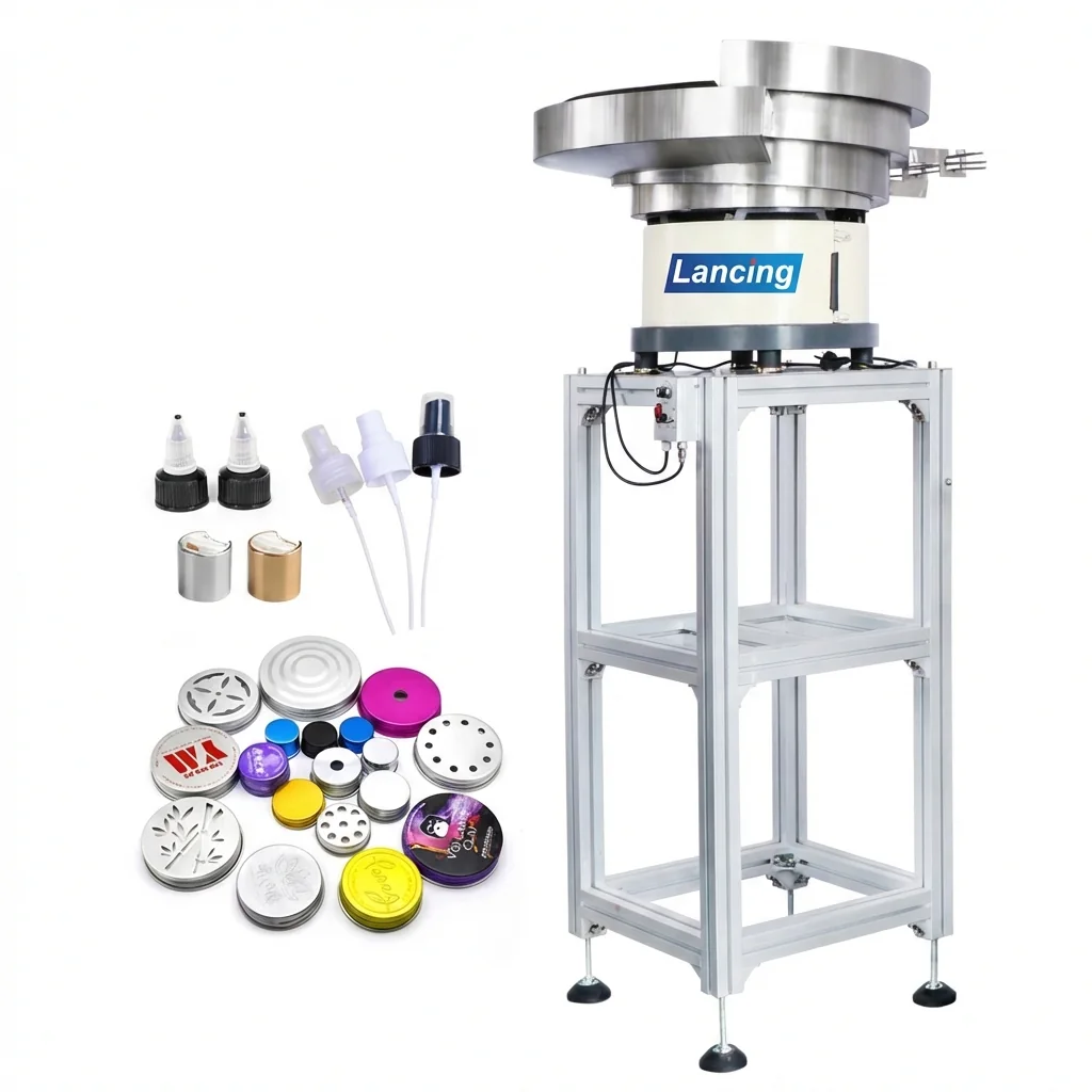
Cap feeder integration is not just a matter of putting a bowl beside a capper. The cap must arrive in the right orientation, at the right height, with enough queue capacity and without blocking access to the machine.
Check capper model, cap handover point, chute route and available space.
Caps should be reviewed for nesting, static, surface finish and orientation features.
The feeder may need to stop when the cap queue is full and restart when the capper calls for caps.
Planning details
These points help Lancing UK narrow the feeder route and avoid a generic specification.
| Area | What matters |
|---|---|
| Samples | Caps, closures, bottles and any variants expected to run. |
| Line data | Target bottles per minute, capper type, running pattern and changeover frequency. |
| Layout data | Photos, drawings, discharge height, access points and utilities. |
| Controls data | Start/stop signal, queue sensor, low-level warning and safety requirements. |
Quick answers
The handover between feeder chute and capper is often the biggest risk if it is not planned early.
Often yes, but physical space, height and controls compatibility must be checked.
Yes. Bottles help confirm cap placement, capper setup and overall line requirements.
Use these pages to compare related feeder options and prepare a stronger quote request.
Send samples, photos, required orientation and target output to Lancing UK.
Practical acceptance criteria
This additional section focuses on mechanical and controls checks between the feeder, chute, capper and line PLC rather than repeating generic automation definitions.
| Briefing area | Evidence to collect | How it helps the feeder decision |
|---|---|---|
| Sample set | Good parts, rejected parts if available, drawings, photos, dimensions, material and finish notes. | Shows how the real component behaves in the bowl, track and reject route. |
| Required output | Target feed rate, line demand, acceptable accumulation and any stop/start sequence. | Prevents over-specifying or under-specifying the bowl, hopper and controller. |
| Orientation and handover | Required exit attitude, discharge height, downstream machine inlet, chute direction and pick point details. | Defines whether the system needs a bowl, linear track, chute, escapement or sensor confirmation. |
| Operating constraints | Noise, static, cleanability, coating, access, guarding, operator refill and maintenance expectations. | Highlights practical limitations before design, quotation and installation. |
If the requirement is a bowl, cap or component feeding project, move from the guide to the matching product route.
View productsIf the requirement starts with the cap, pump, trigger, screw cap or small component, use the application route first.
View applicationsWhen samples and line details are available, send them through the enquiry form so Lancing can assess the route.
Request a quote