Part details
Photos, sample parts, dimensions, weight, material and the required exit orientation.
Product route
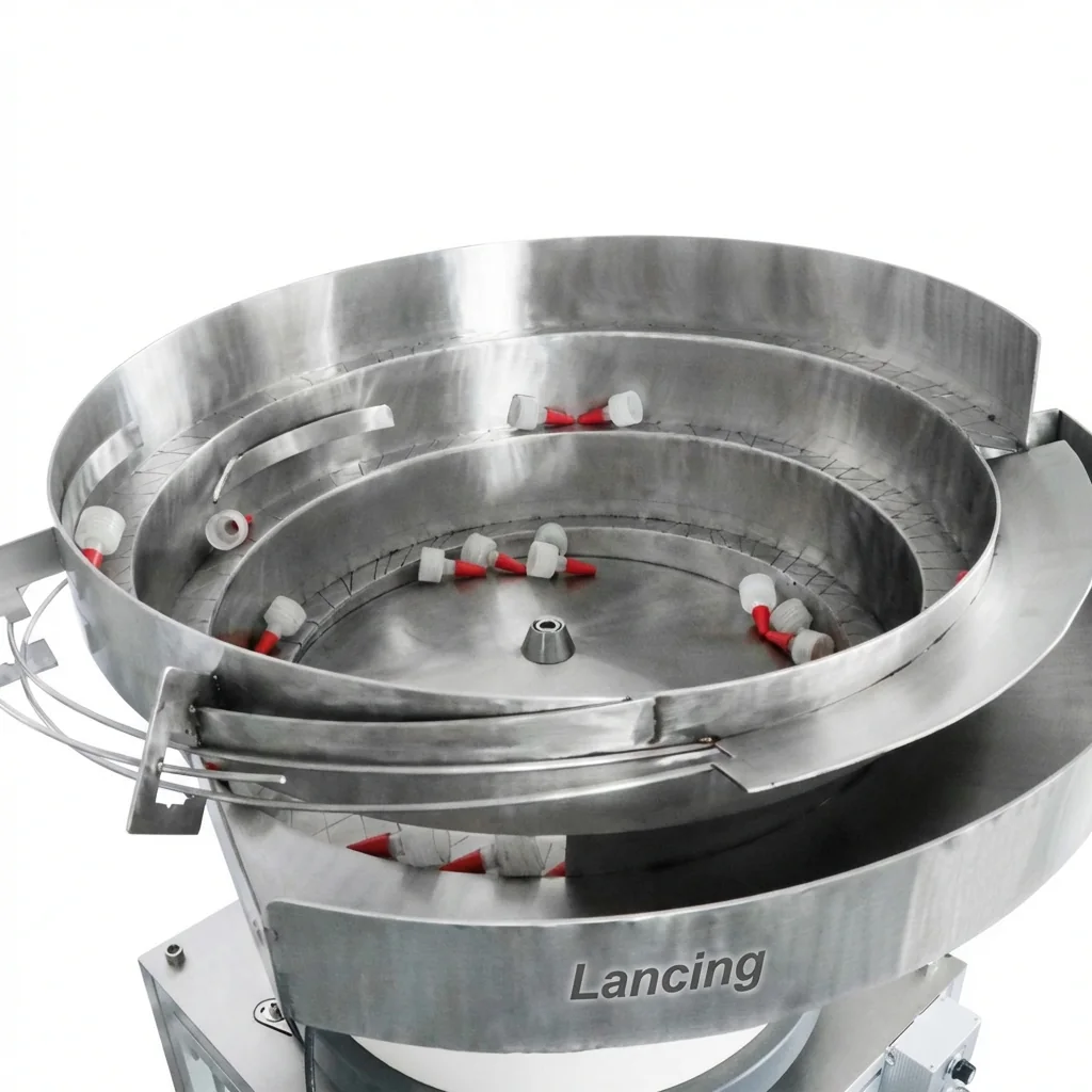
Custom feeder bowls and track tooling designed around your exact part. Suitable for caps, pumps, sprayers, small hardware and component presentation.
Configuration
Final specification is confirmed against part samples, target feed rate, orientation requirement, outlet height, available footprint, utilities and control interface.
Part geometry, material and centre of gravity are assessed before the bowl route is confirmed.
Tooling is used to reject or correct the wrong orientation before the discharge point.
Chute, stand, controls and sensor options are matched to the downstream capper or fixture.
Typical specification
Exact data is confirmed during quotation because feeder performance is part-specific.
| Specification area | Typical requirement |
|---|---|
| Power | 110/220 V, 50–60 Hz subject to final configuration. |
| Construction | Stainless steel bowl and frame options for factory environments. |
| Suitable parts | Caps, closures, pumps, sprayers, small components or application-specific parts. |
| Feed rate | Customised per part, orientation requirement and downstream equipment. |
| Options | Bulk hopper, level sensor, acoustic cover, anti-static lining, special chute or custom stand. |
Quote checklist
Photos, sample parts, dimensions, weight, material and the required exit orientation.
Target parts per minute, downstream machine type and whether the feeder must start/stop with the line.
Available footprint, discharge height, power, air, noise constraints and operator access requirements.
Contact Lancing UK with your component details and target output.
Engineering specification
These notes add the practical information buyers usually need before Lancing can confirm a feeder route, tooling approach and line interface.
Vibratory bowl feeders should be assessed with real samples. Lancing will need the component geometry, material, finish, centre of gravity and the exact orientation needed at the discharge point.
View sample requirementsThe design route considers bowl geometry, spiral track behaviour, tooling gates, orientation rejects and discharge into the downstream machine. Wrongly presented parts may need to be rejected, corrected or recirculated before they reach the downstream equipment.
View tooling guideThe discharge height, chute handover, sensor positions, start/stop signal and PLC interface should be checked before the quotation is finalised.
Integration checklist| Feeder planning point | What to confirm | Why it matters |
|---|---|---|
| Suitable parts | Caps, closures, pumps, sprayers and small repeatable parts | Confirms that this page owns the orientation and feeding problem rather than the complete packaging machine decision. |
| Target rate | Target parts per minute, acceptable surge and whether the feeder must avoid starving or flooding the downstream machine. | The rate is part-specific and should be proven against the actual component and discharge route. |
| Change parts | Which caps, closures or components must run on the same system and how quickly changeover needs to happen. | Some formats can share tooling; others need dedicated bowls, tracks, rails or chutes. |
| Environment | Noise constraints, static risk, product cleanliness, material finish, coating and operator access. | These factors influence bowl lining, covers, sensor selection, guarding and maintenance access. |
These answers are based on the feeder information visible on this site and avoid unsupported speed, price or stock claims.
The useful starting point is sample parts, drawings or dimensions, material, weight, required exit orientation, target feed rate, downstream machine details, discharge height, footprint and any control interface requirements.
Sometimes, but it depends on how close the parts are in size, weight, shape and orientation behaviour. Multi-format use should be checked with real samples and agreed changeover limits.
Geometry, surface finish, weight, nesting behaviour, static, tooling wear, track loading, sensor position, chute handover and the downstream machine demand can all affect consistency.
If the component tangles, marks easily, has no stable orientation features or needs a very different presentation method, a linear feeder, escapement, hopper, magazine or another handling route may be better.
Agree whether the feeder must start and stop from the downstream machine, whether level sensors are required and whether a sensor or PLC interface is needed for jam, full-track or low-part conditions.
The bowl tooling and reject route are designed around the actual part. Samples expose mould variation, coating, static, balance and change-part issues that drawings alone can miss.
Design checks
A vibratory bowl feeder is only successful when the bowl motion, tooling and outlet match the actual part. The following checks help Lancing decide whether the part can be reliably sorted, whether a reject or recirculation route is needed and how the feeder should interface with the line.
Caps and components with uneven weight, handles, hinges, threads or flexible features may tip, bounce or nest differently from a simple round part. Sample parts are used to check how the component naturally sits on the bowl track.
Tooling needs to move the part towards the correct orientation and reject incorrect presentation without creating a jam point. Some rejected parts can recirculate in the bowl; others need careful handling to avoid marks or damage.
The final discharge is where many feeder problems appear. Height, angle, chute length, sensor position and back-pressure all need to suit the capper, escapement, pick point or counting machine.
| Check | Engineering question | Likely effect on specification |
|---|---|---|
| Sample condition | Are all samples from the same mould, supplier and material as production parts? | Reduces the risk of tooling being built around a non-representative sample. |
| Orientation difficulty | Is the required exit position naturally stable or does it need several tooling stages? | Can affect bowl size, track length, reject design and trial time. |
| Surface behaviour | Does the part slide, grip, bounce, generate static or mark easily? | May influence coating, lining, vibration setting, air use or handling route where appropriate. |
| Interface control | Does the downstream machine need a ready signal, low-level signal or stop-start interlock? | Shapes the controller, sensor and PLC interface plan. |
Tooling is designed around real behaviour. Drawings and dimensions help, but samples show how the part slides, tips, rejects and transfers under vibration.
An indicative requirement can be discussed, but a reliable rate depends on the part, tooling, track and downstream machine. Lancing avoids publishing unsupported rate claims without the test context.
The bowl provides the vibratory movement and path. The tooling is the part-specific track, gates, selectors and discharge features that create the required orientation.
If the part is too fragile, too variable, prone to tangling or difficult to orient by vibration, Lancing can review whether a different feeding or presentation route is more appropriate.
Engineering answers
These questions focus on the part behaviour that must be understood before a vibratory bowl and its tooling can be finalised.
A component may settle in several attitudes as it moves around the track. The tooling must preserve or create the required attitude while rejecting the others. Parts with many similar stable positions can need more track length, clearer geometric reference features or a different orientation sequence than parts with one dominant resting position.
The accepted orientation can be described by the downstream machine’s need, but every wrong attitude must also be understood. A robust design identifies how upside-down, side-on, nested or overlapping parts will leave the accepted path and return without blocking the track or damaging components.
Useful output is the sustained number of correctly oriented parts available at the agreed handover point under representative loading and demand. Counting movement inside the bowl can hide rejects, recirculation, gaps, double presentation and downstream blockage, so acceptance evidence should be taken where the receiving machine actually collects the part.
Include normal dimensional tolerances, different mould cavities or suppliers, surface-finish changes, decoration, flash, burrs and any accepted process variation. Tooling proven only with a small set of ideal parts may be too sensitive when normal production variation reaches the feeder.
Proof before build
A custom vibratory bowl feeder should be judged against the actual component, not only the feeder category. Useful evidence shows part flow, orientation, rejection, recirculation and the intended discharge arrangement.
| Evidence | What it should show | Related guide |
|---|---|---|
| Trial video | Parts circulating, orientation features working and the discharge condition being demonstrated. | Trial videos |
| Layout drawing | Bowl position, stand, discharge height, receiving machine and operator access. | Layout planning |
| Safety and access review | Intervention points, guarding expectation, isolation route and connected machine behaviour. | Safety considerations |