Part details
Photos, sample parts, dimensions, weight, material and the required exit orientation.
Product route
A cap feeder keeps the capping machine supplied with correctly oriented closures, reducing manual loading and improving line consistency.
Configuration
Final specification is confirmed against part samples, target feed rate, orientation requirement, outlet height, available footprint, utilities and control interface.
Part geometry, material and centre of gravity are assessed before the bowl route is confirmed.
Tooling is used to reject or correct the wrong orientation before the discharge point.
Chute, stand, controls and sensor options are matched to the downstream capper or fixture.
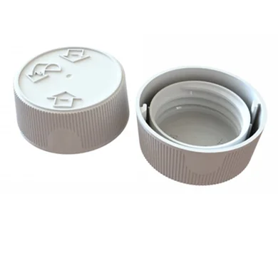
Typical specification
Exact data is confirmed during quotation because feeder performance is part-specific.
| Specification area | Typical requirement |
|---|---|
| Power | 110/220 V, 50–60 Hz subject to final configuration. |
| Construction | Stainless steel bowl and frame options for factory environments. |
| Suitable parts | Caps, closures, pumps, sprayers, small components or application-specific parts. |
| Feed rate | Customised per part, orientation requirement and downstream equipment. |
| Options | Bulk hopper, level sensor, acoustic cover, anti-static lining, special chute or custom stand. |
Quote checklist
Photos, sample parts, dimensions, weight, material and the required exit orientation.
Target parts per minute, downstream machine type and whether the feeder must start/stop with the line.
Available footprint, discharge height, power, air, noise constraints and operator access requirements.
Contact Lancing UK with your component details and target output.
Engineering specification
These notes add the practical information buyers usually need before Lancing can confirm a feeder route, tooling approach and line interface.
Automatic cap feeding systems should be assessed with real samples. Lancing will need the component geometry, material, finish, centre of gravity and the exact orientation needed at the discharge point.
View sample requirementsThe design route considers cap shape, cap depth, closure weight, capper chute handover and line stop/start control. Wrongly presented parts may need to be rejected, corrected or recirculated before they reach the downstream equipment.
View tooling guideThe discharge height, chute handover, sensor positions, start/stop signal and PLC interface should be checked before the quotation is finalised.
Integration checklist| Feeder planning point | What to confirm | Why it matters |
|---|---|---|
| Suitable parts | Screw caps, dispensing caps, pumps, triggers, sprayers and crown closures | Confirms that this page owns the orientation and feeding problem rather than the complete packaging machine decision. |
| Target rate | Target parts per minute, acceptable surge and whether the feeder must avoid starving or flooding the downstream machine. | The rate is part-specific and should be proven against the actual component and discharge route. |
| Change parts | Which caps, closures or components must run on the same system and how quickly changeover needs to happen. | Some formats can share tooling; others need dedicated bowls, tracks, rails or chutes. |
| Environment | Noise constraints, static risk, product cleanliness, material finish, coating and operator access. | These factors influence bowl lining, covers, sensor selection, guarding and maintenance access. |
These answers are based on the feeder information visible on this site and avoid unsupported speed, price or stock claims.
The useful starting point is sample parts, drawings or dimensions, material, weight, required exit orientation, target feed rate, downstream machine details, discharge height, footprint and any control interface requirements.
Sometimes, but it depends on how close the parts are in size, weight, shape and orientation behaviour. Multi-format use should be checked with real samples and agreed changeover limits.
Geometry, surface finish, weight, nesting behaviour, static, tooling wear, track loading, sensor position, chute handover and the downstream machine demand can all affect consistency.
If the component tangles, marks easily, has no stable orientation features or needs a very different presentation method, a linear feeder, escapement, hopper, magazine or another handling route may be better.
Agree whether the feeder must start and stop from the downstream machine, whether level sensors are required and whether a sensor or PLC interface is needed for jam, full-track or low-part conditions.
The bowl tooling and reject route are designed around the actual part. Samples expose mould variation, coating, static, balance and change-part issues that drawings alone can miss.
Capper interface
A cap feeder is normally judged by how smoothly it delivers correctly oriented closures to the capper. The bowl, hopper, chute and controls therefore need to be specified with the capper interface in mind, especially on retrofit lines where height and available space are already fixed.
Screw caps, flip-top caps, pumps, triggers and sprayers behave differently. Hinges, dip tubes, overcaps, ribs and thread starts can all change how the closure orients and transfers.
Pump and trigger feedingThe outlet needs to meet the chute, pick head or cap placement area without flooding, starving or creating back-pressure. Discharge height, angle and sensor positions should be confirmed before a layout is fixed.
Closure feeding to cappersA hopper can reduce manual topping-up, but it must be matched to the bowl capacity and closure behaviour. Level sensors and start-stop control help prevent the bowl from being overfilled.
Cap feeder hoppers| Cap feeder input | Why it matters | Useful evidence to send |
|---|---|---|
| Closure samples | The sample reveals whether the cap nests, flips, marks, generates static or needs additional orientation stages. | Production caps, alternative caps and notes on material or supplier variation. |
| Capping machine interface | The final hand-off determines chute shape, outlet height, sensor logic and stop-start behaviour. | Photos, layout, chute drawings, line speed target and control interface notes. |
| Changeover plan | Multi-cap lines may need settings, change parts or separate tooling depending on closure differences. | All cap sizes, batch frequency and acceptable changeover method. |
| Operating constraints | Noise, static, cleaning access and operator loading height can change the practical specification. | Site photos, hygiene expectations, available footprint and operator access needs. |
Yes. The capper interface affects outlet height, chute shape, control signals and whether caps need to arrive continuously or in a controlled stop-start flow.
Sometimes, but it depends on the closure geometry and orientation route. Pumps, triggers and screw caps often need different tooling or change parts.
A hopper is useful when manual topping-up would interrupt production, but it needs level control so the bowl is not overloaded with caps.
Common causes include inconsistent caps, unsuitable tooling, incorrect vibration setting, poor transfer into the chute, overfilling, static or a downstream capper restriction.
Capper integration
A cap feeder and a capper must be treated as one mechanical and control interface at the handover point.
The cap pickup or placement method, chute inlet, required cap attitude, discharge height, approach direction, permitted queue pressure, machine cycle and request signal all affect the feeder outlet. A drawing or measured interface is more reliable than assuming that two cappers accept caps in the same way.
The cap should arrive in the orientation, spacing and stability required by the capper, with enough control to prevent overlapping or uncontrolled pressure. The final presentation may use a gravity chute, guided track, escapement, cap-present sensor or another interface agreed with the capping-machine owner.
The system should detect that the cap queue or handover is full, pause the appropriate feeder stages and restart in a controlled order when demand returns. The exact sequence depends on the hopper, bowl, track, sensors and capper logic; it should be agreed and tested rather than left to continuous running.
Bottle height, neck position, conveyor datum, capper head location and bottle stability can affect the final cap placement point and the available chute route. Bottle samples or a reliable line drawing can therefore be relevant when the feeder must match an existing capping machine rather than a stand-alone test rig.
Capper interface
For cap feeding systems, the critical detail is often not the bowl alone. The complete route includes bulk loading, bowl orientation, chute condition, level sensing, demand signal, track back-pressure and how the capper reacts when caps are low or wrongly presented.
Send photographs or drawings of the capper chute, placement head, cap track and the current manual-loading point.
Specify the discharge interfaceConfirm whether the capper can call for caps, pause the feeder, detect low caps and stop safely when the line stops.
Sensors and PLC integrationA cap sorting clip should show the cap sample and accepted orientation, but final acceptance still needs the capper interface.
Trial video guide