Why do parts move uphill in a bowl feeder?
The vibration and track angle combine to move parts along the spiral track in a controlled direction.
Guide
A practical explanation of the bowl, vibration, tooling and discharge stages used to turn bulk parts into a controlled feed.
Specification focus
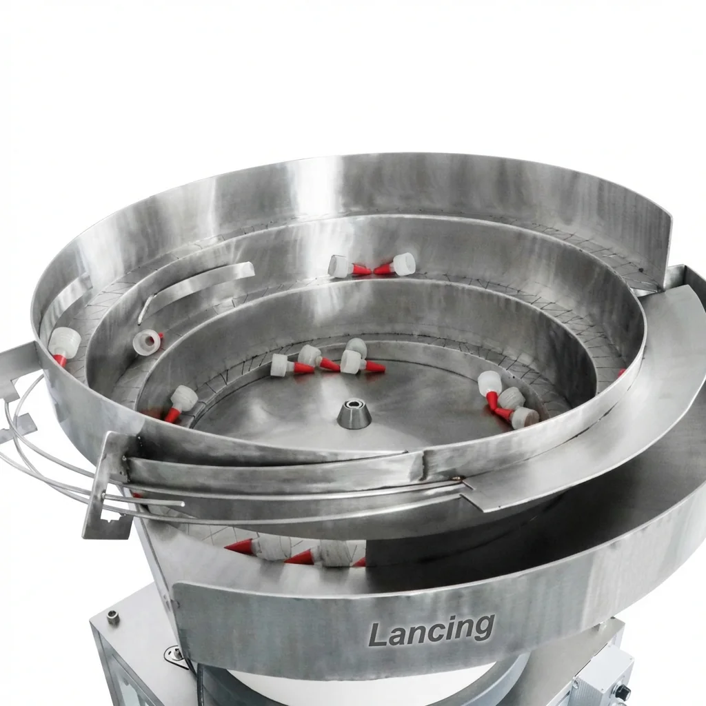
A vibratory bowl feeder uses vibration to move bulk-loaded parts around a spiral track. As parts travel, tooling features reject or correct the wrong orientation until only correctly presented parts continue to the discharge point.
Parts are placed into the bowl manually or through a hopper.
The feeder drive moves parts along the track at a controlled rate.
Orientation tooling filters the parts before they leave the bowl through a chute or track.
Planning details
These points help Lancing UK narrow the feeder route and avoid a generic specification.
| Area | What matters |
|---|---|
| Bowl | Holds and moves bulk parts around the spiral track. |
| Tooling | Rejects, turns, separates or guides parts based on shape and balance. |
| Linear track or chute | Transfers oriented parts to the downstream machine or pick point. |
| Controller | Adjusts vibration and can integrate with sensors or line signals. |
Quick answers
The vibration and track angle combine to move parts along the spiral track in a controlled direction.
Tooling uses part features such as lips, holes, ribs, weight and centre of gravity to reject or guide parts.
Parts that tangle, nest, bounce, mark easily or have few orientation features can be harder to feed reliably.
Use these pages to compare related feeder options and prepare a stronger quote request.
Send samples, photos, required orientation and target output to Lancing UK.
Practical acceptance criteria
This additional section focuses on how vibration, tooling, track geometry and reject points create repeatable part orientation rather than repeating generic automation definitions.
| Briefing area | Evidence to collect | How it helps the feeder decision |
|---|---|---|
| Sample set | Good parts, rejected parts if available, drawings, photos, dimensions, material and finish notes. | Shows how the real component behaves in the bowl, track and reject route. |
| Required output | Target feed rate, line demand, acceptable accumulation and any stop/start sequence. | Prevents over-specifying or under-specifying the bowl, hopper and controller. |
| Orientation and handover | Required exit attitude, discharge height, downstream machine inlet, chute direction and pick point details. | Defines whether the system needs a bowl, linear track, chute, escapement or sensor confirmation. |
| Operating constraints | Noise, static, cleanability, coating, access, guarding, operator refill and maintenance expectations. | Highlights practical limitations before design, quotation and installation. |
If the requirement is a bowl, cap or component feeding project, move from the guide to the matching product route.
View productsIf the requirement starts with the cap, pump, trigger, screw cap or small component, use the application route first.
View applicationsWhen samples and line details are available, send them through the enquiry form so Lancing can assess the route.
Request a quote